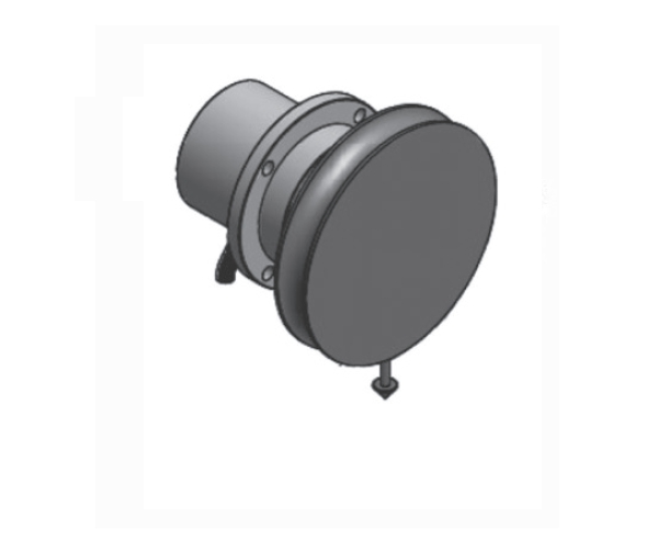
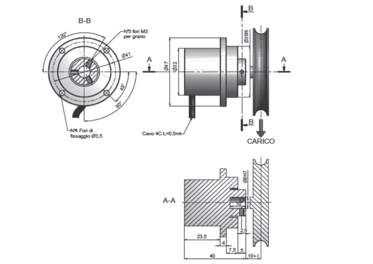
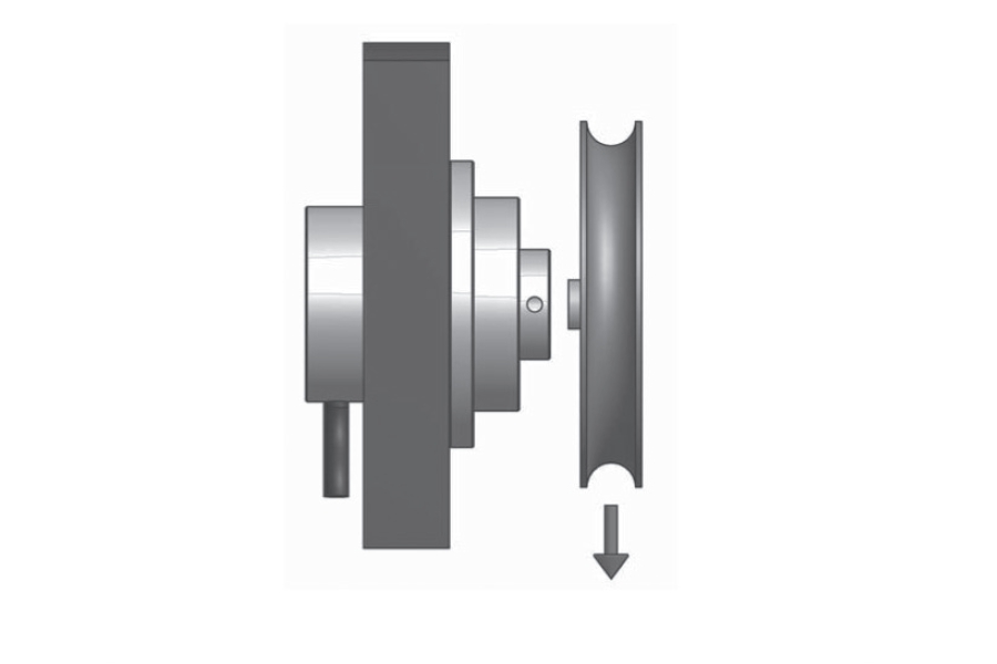
PULLEY LOAD CELL
Features: Compact, excellent resolution. Easy to assemble, high resonant frequency. Protection against overloads.
Applications:coil winding machines, winding machines, unwinding machines, wire tensioner for any applications that have to measure the tension of wires, tapes, optical fibres, tessil wires, etc.
![]() Click to enlarge image
Click to enlarge image


| Material | Aluminium |
| Nominal load | 2.5, 5, 10, 25, 50, 100, 200 N |
| Limit load | 300 % F.S. |
| Breaking load | 500 % F.S. |
| Supply voltage | Maximum 18 V dc |
| Sensitivity | 0,6 - 1 mV/V |
| Output tollerance | 0,2 % F.S. |
| Zero tollerance | 1 % F.S. |
| Linearity | 0,1 % F.S. |
| Hysteresis | 0,2 % F.S. |
| Reapeatability | 0,2 % F.S. |
| Input resistance | 350-360 ohm |
| Output resistance | 350-353 ohm |
| Insulation resistance | >= 2000 Mohm |
| Creep (30 Minutes) | 0,03 % F.S. |
| Thermal compensation | -10 / +40°C (14 / +104°F) |
| Operating temperature | -20 / +70°C (-4 / +158°F) |
| Temperature deviation zero | 0,003 % F.S. / °C |
| Temperature deviation full scale | 0,002 % F.S. / °C |
| Protection class | IP 54 |
| Standard cable length | 3 m – 4 x 0,15 (shield not connected to the load cell body) |
| Type | SHIELDED CABLE PVC 4C R3 4X0,15 |
| Length | 3 m (body lead cell not connected shield) |
| Red | + IN |
| Black | - IN |
| Green | + OUT |
| White | - OUT |
General precautions to be followed in the installation and assembly of load cells: